
Low Volt Wiring – Unit 3
Low Volt Wiring – Unit 3
Regardless of which method of termination, you must safely and legally get the wire from the panel out to each device or from device to device. The number 1 cause of work-related injuries are falls. Be sure to use the proper ladders and use them safely.
The construction of the building and the current draw of your devices will determine the size, conductors and if General Purpose, Plenum or Riser rated wire is required.
General Purpose Wire – A PVC based wire that puts off a toxic smoke when burning. This wire is not allowed to penetrate between floors of a building.
Riser Rated Wire – A PVC based wire that puts off a toxic smoke when burning. The wire will not burn upward. The jacket of the wire will fall off and extinguish itself. The wire is labeled CMR. This wire can be used for floor penetrations.
Plenum Rated Wire – This wire is not oil or PVC based. It does not put off toxic smoke. This wire can penetrate floors. This is the only wire permitted to be used in a Plenum Airspace. The plenum airspace is the area above the suspended ceiling or under computer room floors that are used for air circulation. The wire is labeled as CMP.
(Keep your plenum rated warm. Using frozen plenum wire could cause massive jacket disintegration and your wires may be shorted).
The equipment requirements and building size determine the “Gauge” or size of the wire and number of conductors. This wire is expressed as a wire size or gauge, followed by the number of conductors in the cable. For example, a card reader usually requires a 22/6 or 18/6 cable. A motion sensor uses a 18/4 or 22/4 wire. Door contacts can operate using a 22/2. I would still run a 22/4 just in case some of your wires are damaged.
Access control hardware such as mag locks, electric strikes and electric door hardware need a minimum of 18-gauge wire. A 18/2 or 18/4 wire is commonly used to power locking devices. CAT 5 cables use 24-gauge wire. Category 6 cable uses 23ga. wire. The larger the wire gauge number, the smaller the wire size.
One more consideration is solid or stranded wire. Solid wire is one conductor. Stranded wire is multiple wrapped strands. Solid wire may be a little less expensive, but stranded wire is more flexible and is less susceptible to breakage when flexed. Most technicians like stranded. Use your own preference.
Most Access control systems have on-board, Form C relays. Our systems use relays, switches and timers to control door locks, temporarily shunt door contacts, turn on lights, and many other applications. When a switch is flipped or a relay is energized, the action can be Momentary or Maintained. A momentary switch is a doorbell button. A maintained switch is a light switch. The difference between a relay and a switch is the means of operation. A relay uses electricity. A switch is manually operated.
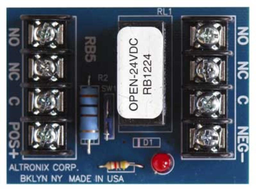
This relay is a Form C Relay. It has a Common, Normally Closed and Normally Open terminal on each side of the board. The Common terminal alternates between the Open and Closed terminals. This example has 2 relays that operate when power is applied to the Pos (+) and Negative (-) terminals.
* When power is applied to the relay, no power is transferred to the C, N/O, or N/C terminals. They just change their normal positions. When power is removed, they return to their original positions.
When Powered: Common and Normally Closed Terminals … OPEN.
When Powered: Common and Normally Open Terminals…. CLOSE.
Double Pole Double Throw Relay
(Another way to say… 2 Form C Relays)
In low volt electrical wiring, Relays control one side of the power to the device (usually Positive). The relay opens and closes as required to control the access control point. The power that energizes the relay is controlled by the access or security system.
A Form C Relay is a point on the system that “Makes” or “Breaks” Positive Power to the controlled device. The required Negative Power is terminated directly to the (-) Negative or Black side of the power supply.
The diagrams below show what happens internally when a relay is energized.
 This control is accomplished using the (+) Positive from the Power Supply wired to the (C) Common of the Form C relay.
Once the (+) Positive “Leg” of our power source is terminated to the common point on the relay, it can be controlled with a button, a switch or by applying power to the relay. This action causes the normally open and normally closed terminals to reverse.
If your lock is an Electrically Unlocked device, terminate the Red or Positive wire to the Normally Open N/O terminal. Even though (+) power is still present on the Common terminal, our device remains locked with no positive power. When the correct code or card is presented, the relay closes and power flows to the device for as long as the relay is programmed to be energized.
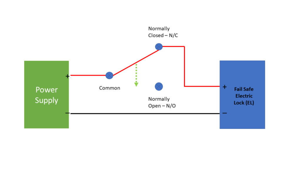
Your “Fail Safe” magnetic or electric lock is wired to the Normally Closed terminal. Since the Positive and Normally Closed terminals on this relay allow the flow of electricity, power will energize the device. When a valid card or code is presented, the relay will open and stop the positive side of the 12 or 24 volts from reaching the device. This will cause the door to unlock.
Access control systems usually have adjustable times for their relay closure. The keypad or card reader controls the amount of time a door is unlocked using programming or software.
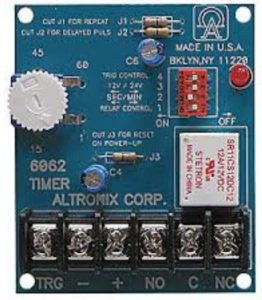
When you need a time range that exceeds the software limits, a timer relay can be added. This type of relay can hold a door unlocked for up to an hour. It’s used in multiple situations where a momentary button push can keep a door unlocked.
When specifying electrified door hardware, the locks and electric strikes can be specified to be Fail Safe or Fail Secure. Fail Safe or Electrically Locked (EL) hardware requires power to become secure. All mag locks are Fail Safe or EL.
Fail Secure door hardware requires power to unlock. Fail Secure or Electrically Unlocked (EU) hardware is common for exterior doors and most electric strike applications.
Regardless of the voltage a device requires or if it’s Electrically locked or Unlocked, our systems must provide the control to unlock the access control point. Electronic Access Control and Security Systems use relays and outputs to electrically control these devices.
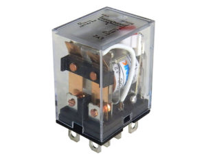
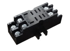
Ice Cube Relay and Socket
This relay can provide high voltage and amperage control using a 12 VDC or 24VDC power source.