Low Volt Wiring – Unit 2
Low Volt Wiring – Unit 2
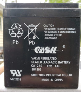
So… What is an Amp-Hour?
It is a measurement of the time required to drain the available current out of a back up battery after A/C failure. It is based on the sum of all the current used by the devices that are connected to the system. Each device on the system that requires constant power must be included in the calculation. This is known as “Current Drain”
Door contacts don’t require power to operate. No current drain. A Fail Secure Electric Strike (EU) has no current drain. A magnetic lock, motion sensor, card reader, timed exit buttons, glass-break, keypads and the control panel all draw battery power when A/C is removed.

A common analogy used to explain the relationship between voltage and amps is water. Volts are the size of the water pipe and Amps are the water pressure. A 2-inch water pipe (24 Volts) will double the amount of water in a 1-inch pipe (12 Volts). Although size does matter, security equipment can’t do anything without the force, pressure, current, or amperage required to make all your devices operate as required. This force, Amperage or Amps is the total pool of power available at 12vdc or 24vdc.
Add up the current draw of each device and it should be lower than the total amperage available. The total current draw of all your devices added together, shouldn’t exceed 80% of the total amperage rating of the power supply.
When the Voltage is doubled from 12VDC to 24VDC, ½ the current (amps) is required to power the equipment. Regardless of the voltage, the “Current Draw” of each device must be added together to determine the total current draw and size of the power supply that’s required. (This can be expressed in the formula P = I*E, where P is power or watts and I is Current, and E is Volts).
Example: An electric strike draws .24 amps @ 12VDC. When powered by 24VDC, it only needs .12 amps to operate.
Electric hardware like electric strikes, electric locks and panic devices use solenoids to mechanically unlock the hardware. These solenoids extend or retract to provide the required locking function. Each time the device is de-energized, the built-up electrical charge is sent back to your control relay. After repeated spikes from the locks, damage to the relay can occur. We use Diodes to protect the equipment.

Diodes are a one-way, surge control device. It is placed between the positive and negative connections as close to the electric lock as possible. The stripe on the diode must be terminated to the positive side. The diode is also known as a Transorb.
The quality of our equipment has improved with time and innovation. Electrical surges aren’t destroying equipment at the rate that was once occurring. Regardless who makes the equipment, providing a quality path to ground will help keep it working when the power surges arrive.
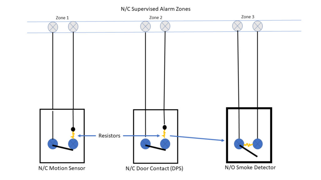
In the security industry, Resistors are mainly used as a means of measuring the resistance value of a “Normally Open” or “Normally Closed” “Supervised Loop”. A supervised loop (or Zone) are two points in the control panel where you can take a measurement and verify that the alarm device at the end of the wire is open or closed. This device could be a motion sensor, a door contact (DPS), or a panic button. What makes it supervised is the resistor. The (EOLR) End of Line Resistor, has value specified by each manufacturer that allows their system to verify integrity of the entire wire run. The EOLR MUST be placed at the last device in the zone.

When a N/C device senses motion, an open door or glass is broken, the relay opens, and the alarm system loses the resistance value it was monitoring. When a smoke alarm is activated, the device closes, and the alarm is sent. Notice each resistor tells the system the Zone is secure.
Most systems in the security industry use Normally Closed Zones. Fire systems use Normally Open zones or loops.
The Normally Closed Zone wiring allows alarm panels to see 2 conditions, Open and Closed, (Secured or Unsecured).
Normally Open Zone wiring used by Fire Alarm Systems allow 3 different conditions to be monitored. Normal (Open Circuit with Resistor), Alarm (Shorted), and Trouble (Open Circuit Without Resistor).
