Low Volt Wiring
This course is designed to educate technicians in low volt aspects of access control and security systems. The subjects and terminology of this course is meant to cover many of the basic and advanced wiring scenarios we as technicians face daily.
Our installations are custom. Rarely does a “kit” cover the all the devices required for an access or security installation. Relays, timers, switches, motion sensors and other input devices are mandatory elements of a secure system. Sirens, electric strikes and mag locks are examples of devices that are controlled by a system’s output.
Example: A card reader is an input device. Upon a valid card read, the system will energize the required relay or output to control the locking hardware.
Before we wire up our system, let’s look at the terminology and concepts we need to be aware of to make it work now and far into the future.
Alternating Current A/C is the power source we use to turn on our alarm panels, access control systems and power supplies. The power supplies often use 120 volts hard wired or by way of a plug-in cord. Alarm systems and many access control systems use a 16VAC plug-in transformer to power up the equipment. These systems may also have a 12VDC output available to power a limited number of devices.
Regarding access control and security power, two of the most important considerations are voltage and amperage. Our industry uses 12 volts DC and 24 volts DC to power our sirens, mag locks, strobes, electric strikes, relays and timers. Each of these devices has a power requirement of 12 VDC, 24 VDC or a range that includes both voltages. If the voltage requirement of each device matches the voltage of the power supply, the system should operate.
To make sure it does operate, the other factor we need to consider is Amperage (or Current). Amperage or Amps is the amount of power behind the voltage. (Add too many devices to your system and it won’t work regardless of the voltage). The voltage is a rating. 12 or 24 VDC. It is chosen based upon the size of the building and the power required by the devices connected to the system. Devices can be backed up by a 12VDC battery. If 24 VDC battery back-up is required, two 12VDC batteries will need to be wired together “in series”.
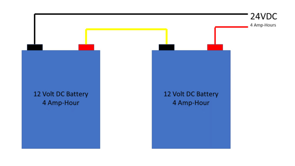
In Series means the devices you terminate are added together like the batteries in a flashlight. One AA, AAA, C or D battery is 1.5 volts DC. The batteries are inserted so the positive and negative terminals touch. They are inserted in-series. With 3 batteries, you get 4.5 VDC. With 4 batteries, 6 volts DC is the total power.
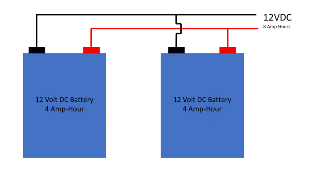
In Parallel, connections are made by terminating all the positive points together and all the negative points together. If we are using 12-volt batteries, we end up with 12 volts DC as the total output voltage. We didn’t increase the voltage; we made our existing voltage last twice as long.
The terms In-Series and In-Parallel don’t just apply to battery power. Burglar Alarm system devices like window contacts, are sometimes wired in-series. This is also known as a Normally Closed Loop. All devices should have their own unique wire home run (no splices) back to the control panel. Wiring more than 1 device on a wire may make troubleshooting more difficult. Which device caused the fault?
Fire alarm system devices are wired Normally Open. Their wiring is run in-parallel. A resistor is placed in at the end of the line, inside the last input device, to monitor the circuit. Wiring configurations such as addressable loops, wireless and other new technologies require knowledge of the products we’re installing before the 1st wire is run.
So… What is an Amp-Hour?
It is a measurement of the time required to drain the available current out of a back up battery after A/C failure. It is based on the sum of all the current used by the devices that are connected to the system. Each device on the system that requires constant power must be included in the calculation. This is known as “Current Drain”
Door contacts don’t require power to operate. No current drain. A Fail Secure Electric Strike (EU) has no current drain. A magnetic lock, motion sensor, card reader, timed exit buttons, glass-break, keypads and the control panel all draw battery power when A/C is removed.

A common analogy used to explain the relationship between voltage and amps is water. Volts are the size of the water pipe and Amps are the water pressure. A 2-inch water pipe (24 Volts) will double the amount of water in a 1-inch pipe (12 Volts). Although size does matter, security equipment can’t do anything without the force, pressure, current, or amperage required to make all your devices operate as required. This force, Amperage or Amps is the total pool of power available at 12vdc or 24vdc.
Add up the current draw of each device and it should be lower than the total amperage available. The total current draw of all your devices added together, shouldn’t exceed 80% of the total amperage rating of the power supply.
When the Voltage is doubled from 12VDC to 24VDC, ½ the current (amps) is required to power the equipment. Regardless of the voltage, the “Current Draw” of each device must be added together to determine the total current draw and size of the power supply that’s required. (This can be expressed in the formula P = I*E, where P is power or watts and I is Current, and E is Volts).
Example: An electric strike draws .24 amps @ 12VDC. When powered by 24VDC, it only needs .12 amps to operate.
Electric hardware like electric strikes, electric locks and panic devices use solenoids to mechanically unlock the hardware. These solenoids extend or retract to provide the required locking function. Each time the device is de-energized, the built-up electrical charge is sent back to your control relay. After repeated spikes from the locks, damage to the relay can occur. We use Diodes to protect the equipment.

Diodes are a one-way, surge control device. It is placed between the positive and negative connections as close to the electric lock as possible. The stripe on the diode must be terminated to the positive side. The diode is also known as a Transorb.
The quality of our equipment has improved with time and innovation. Electrical surges aren’t destroying equipment at the rate that was once occurring. Regardless who makes the equipment, providing a quality path to ground will help keep it working when the power surges arrive.
In the security industry, Resistors are mainly used as a means of measuring the resistance value of a “Normally Open” or “Normally Closed” “Supervised Loop”. A supervised loop (or Zone) are two points in the control panel where you can take a measurement and verify that the alarm device at the end of the wire is open or closed. This device could be a motion sensor, a door contact (DPS), or a panic button. What makes it supervised is the resistor. The (EOLR) End of Line Resistor, has value specified by each manufacturer that allows their system to verify integrity of the entire wire run. The EOLR MUST be placed at the last device in the zone.
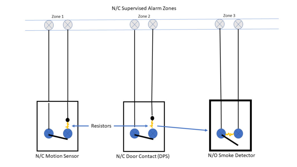
When a N/C device senses motion, an open door or glass is broken, the relay opens, and the alarm system loses the resistance value it was monitoring. When a smoke alarm is activated, the device closes, and the alarm is sent. Notice each resistor tells the system the Zone is secure.
Most systems in the security industry use Normally Closed Zones. Fire systems use Normally Open zones or loops.
The Normally Closed Zone wiring allows alarm panels to see 2 conditions, Open and Closed, (Secured or Unsecured).
Normally Open Zone wiring used by Fire Alarm Systems allow 3 different conditions to be monitored. Normal (Open Circuit with Resistor), Alarm (Shorted), and Trouble (Open Circuit Without Resistor).
Regardless of which method of termination, you must safely and legally get the wire from the panel out to each device or from device to device. The number 1 cause of work-related injuries are falls. Be sure to use the proper ladders and use them safely.
The construction of the building and the current draw of your devices will determine the size, conductors and if General Purpose, Plenum or Riser rated wire is required.
General Purpose Wire – A PVC based wire that puts off a toxic smoke when burning. This wire is not allowed to penetrate between floors of a building.
Riser Rated Wire – A PVC based wire that puts off a toxic smoke when burning. The wire will not burn upward. The jacket of the wire will fall off and extinguish itself. The wire is labeled CMR. This wire can be used for floor penetrations.
Plenum Rated Wire – This wire is not oil or PVC based. It does not put off toxic smoke. This wire can penetrate floors. This is the only wire permitted to be used in a Plenum Airspace. The plenum airspace is the area above the suspended ceiling or under computer room floors that are used for air circulation. The wire is labeled as CMP.
(Keep your plenum rated warm. Using frozen plenum wire could cause massive jacket disintegration and your wires may be shorted).
The equipment requirements and building size determine the “Gauge” or size of the wire and number of conductors. This wire is expressed as a wire size or gauge, followed by the number of conductors in the cable. For example, a card reader usually requires a 22/6 or 18/6 cable. A motion sensor uses a 18/4 or 22/4 wire. Door contacts can operate using a 22/2. I would still run a 22/4 just in case some of your wires are damaged.
Access control hardware such as mag locks, electric strikes and electric door hardware need a minimum of 18-gauge wire. A 18/2 or 18/4 wire is commonly used to power locking devices. CAT 5 cables use 24-gauge wire. Category 6 cable uses 23ga. wire. The larger the wire gauge number, the smaller the wire size.
One more consideration is solid or stranded wire. Solid wire is one conductor. Stranded wire is multiple wrapped strands. Solid wire may be a little less expensive, but stranded wire is more flexible and is less susceptible to breakage when flexed. Most technicians like stranded. Use your own preference.
Most Access control systems have on-board, Form C relays. Our systems use relays, switches and timers to control door locks, temporarily shunt door contacts, turn on lights, and many other applications. When a switch is flipped or a relay is energized, the action can be Momentary or Maintained. A momentary switch is a doorbell button. A maintained switch is a light switch. The difference between a relay and a switch is the means of operation. A relay uses electricity. A switch is manually operated.
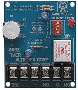
This relay is a Form C Relay. It has a Common, Normally Closed and Normally Open terminal on each side of the board. The Common terminal alternates between the Open and Closed terminals. This example has 2 relays that operate when power is applied to the Pos (+) and Negative (-) terminals.
* When power is applied to the relay, no power is transferred to the C, N/O, or N/C terminals. They just change their normal positions. When power is removed, they return to their original positions.
When Powered: Common and Normally Closed Terminals … OPEN.
When Powered: Common and Normally Open Terminals…. CLOSE.
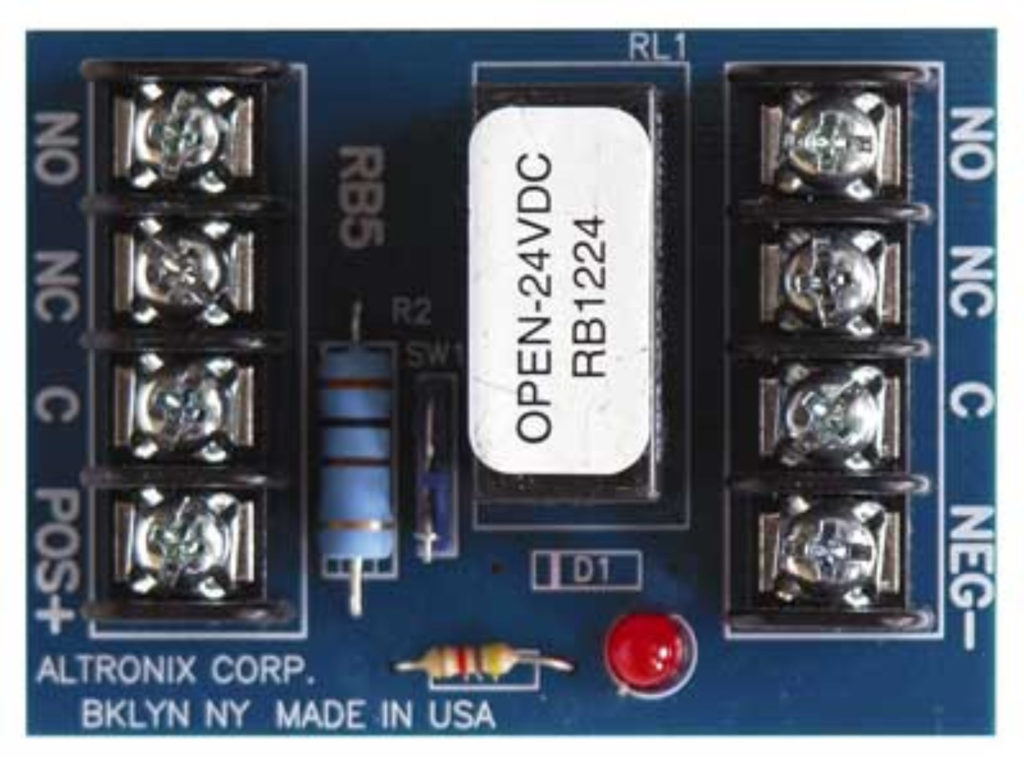
Double Pole Double Throw Relay
(Another way to say… 2 Form C Relays)
In low volt electrical wiring, Relays control one side of the power to the device (usually Positive). The relay opens and closes as required to control the access control point. The power that energizes the relay is controlled by the access or security system.
A Form C Relay is a point on the system that “Makes” or “Breaks” Positive Power to the controlled device. The required Negative Power is terminated directly to the (-) Negative or Black side of the power supply.
The diagrams below show what happens internally when a relay is energized.
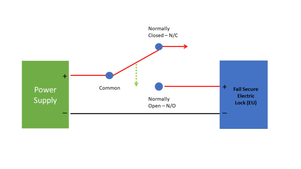 This control is accomplished using the (+) Positive from the Power Supply wired to the (C) Common of the Form C relay.
Once the (+) Positive “Leg” of our power source is terminated to the common point on the relay, it can be controlled with a button, a switch or by applying power to the relay. This action causes the normally open and normally closed terminals to reverse.
If your lock is an Electrically Unlocked device, terminate the Red or Positive wire to the Normally Open N/O terminal. Even though (+) power is still present on the Common terminal, our device remains locked with no positive power. When the correct code or card is presented, the relay closes and power flows to the device for as long as the relay is programmed to be energized.
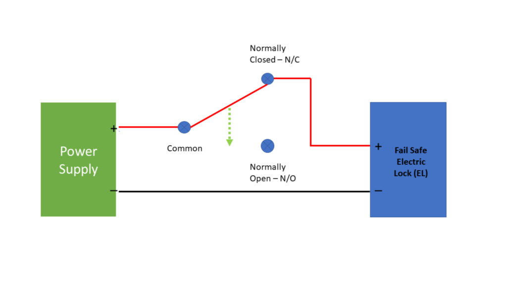
Your “Fail Safe” magnetic or electric lock is wired to the Normally Closed terminal. Since the Positive and Normally Closed terminals on this relay allow the flow of electricity, power will energize the device. When a valid card or code is presented, the relay will open and stop the positive side of the 12 or 24 volts from reaching the device. This will cause the door to unlock.
Access control systems usually have adjustable times for their relay closure. The keypad or card reader controls the amount of time a door is unlocked using programming or software.
When you need a time range that exceeds the software limits, a timer relay can be added. This type of relay can hold a door unlocked for up to an hour. It’s used in multiple situations where a momentary button push can keep a door unlocked.
When specifying electrified door hardware, the locks and electric strikes can be specified to be Fail Safe or Fail Secure. Fail Safe or Electrically Locked (EL) hardware requires power to become secure. All mag locks are Fail Safe or EL.
Fail Secure door hardware requires power to unlock. Fail Secure or Electrically Unlocked (EU) hardware is common for exterior doors and most electric strike applications.
Regardless of the voltage a device requires or if it’s Electrically locked or Unlocked, our systems must provide the control to unlock the access control point. Electronic Access Control and Security Systems use relays and outputs to electrically control these devices.
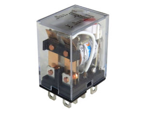
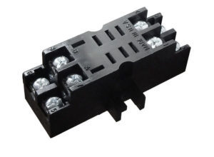
Ice Cube Relay and Socket
This relay can provide high voltage and amperage control using a 12 VDC or 24VDC power source.
Sometimes our keypads and card readers control Panic or Exit devices with Electric Latch Retraction (ELR). Usually these high current devices have their own power supplies. We don’t try to energize the lock with our system. We just send a Normally Open, two conductor (input) wire to the power supply input terminals *(REX). When the correct card is presented, our C and N/O terminals close. The power supply sees the close across its own input terminals. Power is then sent to the panic bar and the door is unlocked.
*Request To Exit (REX) is an input that energizes the main relay to add or remove power to a device like an electric strike or mag lock.
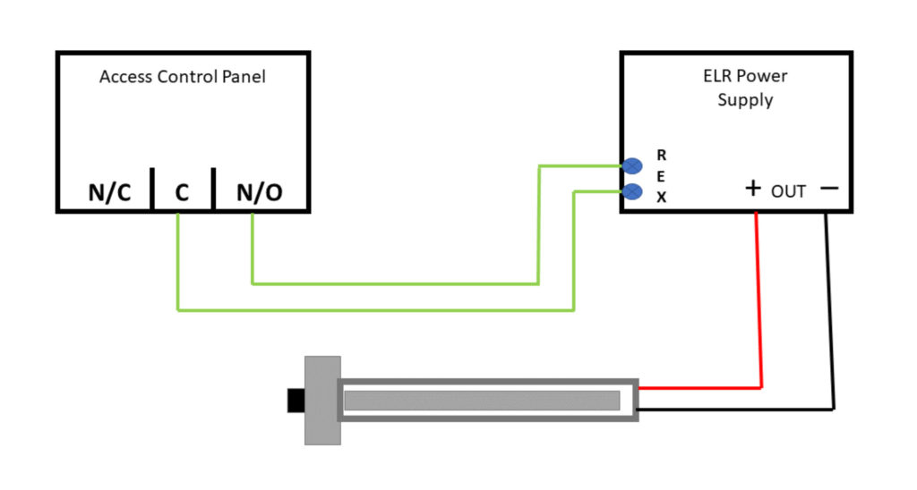
An Output provides both Positive and Negative power when the control energizes the input terminals. 12 or 24 VDC is then sent out to the connected devices. Example: The siren terminals of a small alarm system are usually wired to an output. Power is sent during an alarm. Some access control systems use outputs to control the lock hardware. Some power supplies use N/O inputs from the access control panel, to control a power output to the lock devices.
Wiring Diagrams
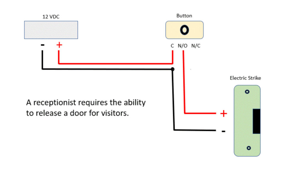
In this scenario, a technician needs to install and wire an electric strike door release. This is a common request. There are many facilities that need to control customer access. A keypad or card reader could be added for employee access.
A wire is run from the electric strike and from the power supply to the button. At the button, the black wires are terminated to each other. The positive (Red) wire from the power supply is terminated to the common. The positive (Red) wire from the electric strike is terminated to N/O button.
As stated earlier, the Common and Normally Open terminals don’t connect naturally. It requires the button to be pushed. Power is now connected as long as the button is depressed. In a nursing home, the button may need to be held for quite a bit while the resident slowly moves toward the door. You might want to consider adding a timer module. See next…
Wiring Diagrams
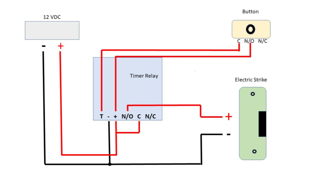
Once again, Grampa wants to get through the door but it’s going to take him a minute to get there. Adding a timer will allow the door to stay energized for an extended period of time with a single push of a button.
Power is run from the power supply, electric strike and button to the timer relay. At the timer, positive and negative power is terminated. The negative of the electric strike is connected to the same – terminal. The Positive from the strike is terminated to the N/O (Normally Open) position on the relay. At this point, there is no Positive wire terminated to the Common on the relay. We must provide a short jumper from the Positive terminal to the Common. The relay is now ready to energize the electric strike for up to an hour.
Almost Finished! The button is your control. Run a pair of wires to the timer. Terminate your normally open wired button to the Positive and the Trigger. A button push provides the closure the timer needs to begin its cycle. The door remains unlocked for the programmed time and the nurse can get back to the real work.
Wiring Diagrams
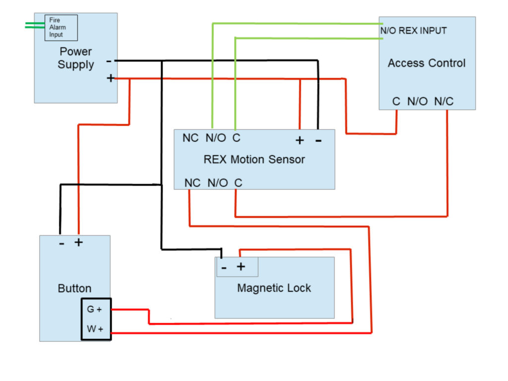
This 1 door scenario has 5 different devices needed to install a controlled opening.
1 – Power Supply with Fire Alarm over-ride, 1 – Access Control Panel Relay, 1 – REX Motion Sensor, 1 – Securitron Timed Egress Button and 1 – Magnetic Lock.
The access control system, motion sensor and button are all powered with continuous power. The Negative (Black) of the mag lock is powered by the same power supply.
From our previous discussion, you understand how a normally closed relay works, right? The positive power is supplied to the Common Terminal. The Normally Closed terminal allows power to flow continuously. After leaving the control panel, the mag lock positive feed is terminated to the common on 1 relay in the motion sensor. Power is continuous in and out of the motion. The button is Normally Closed. It also transfers continuous power to the mag lock positive wire.
Now that the magnetic lock is energized, any valid card read, motion sensor movement or button depress will break Positive power and unlock the door.
In this example, the motion breaks the mag lock power directly. Some technicians use the 2nd motion sensor relay to send a signal back to the control panel and have the panel unlock the mag lock. Using both methods is called “Double Break Wiring”.
